Ostatnio bawiłem się wyświetlaczem LCD z kontrolerem HD44780 (czyli takim kontrolerem, jaki zwykle mają wyświetlacze LCD). Okazuje się, że da się wyświetlać na nim napisy nie używając Arduino, komputera ani żadnej innej mądrej elektroniki. Wystarczy podłączać baterię przewodami do jego nóżek, w ten sposób z palca wysyłać polecenia do kontrolera i wyświetlać, co się chce. Ponieważ (z tego co wiem) nie jest to opisane nigdzie w Internecie, w niniejszym opisie opisuję, jak to zrobić.
Recently I played with LCD display with HD44789 controller. I found out that it is possible to make it display texts without using Arduino, computer or any other smart electronics. You can just connect batteries to its pins, use it to send commands to the controller and the display displays anything you want. As far as I know it is not described anywhere on the Internet, so in this document I describe how to do it.
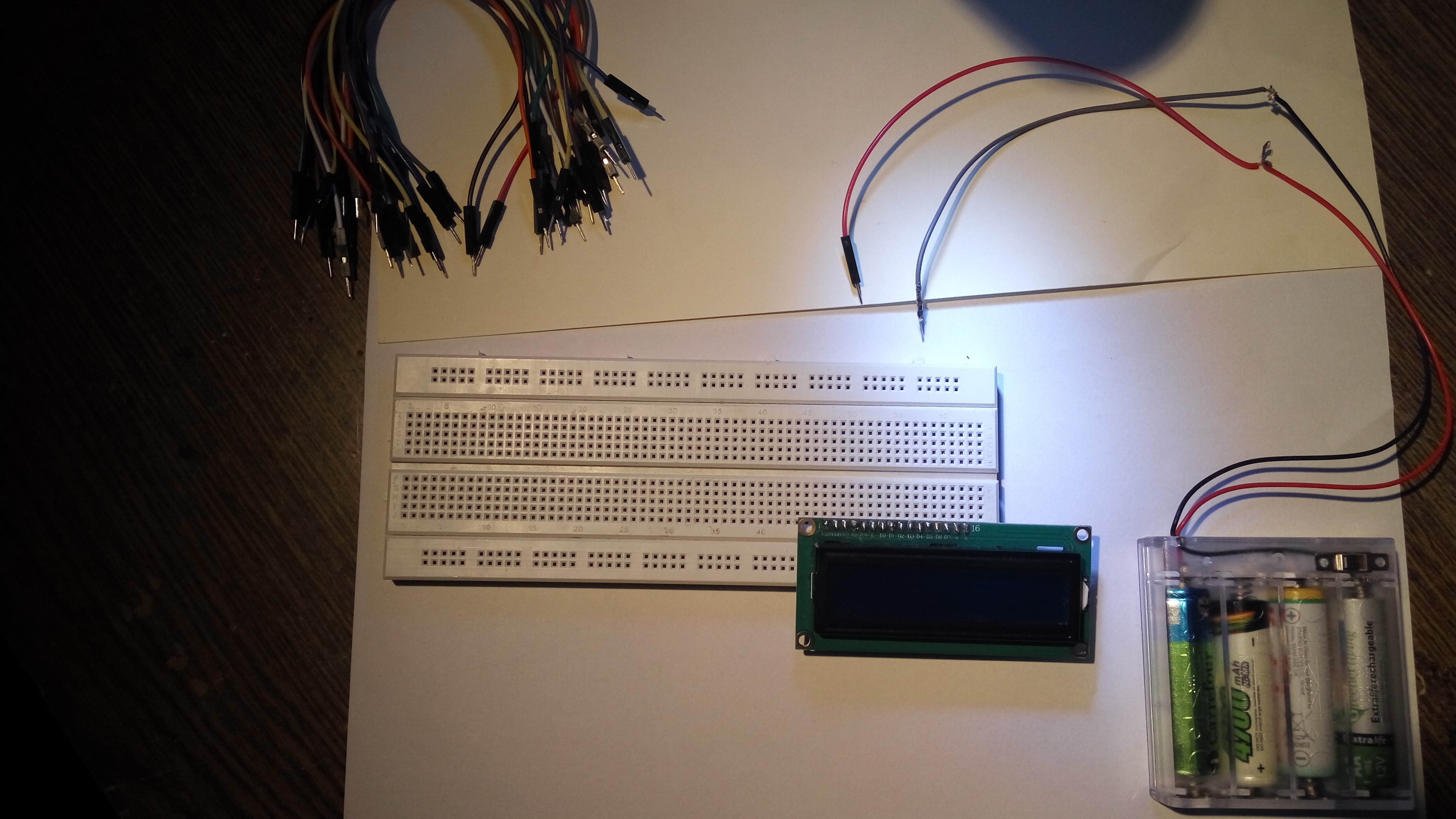
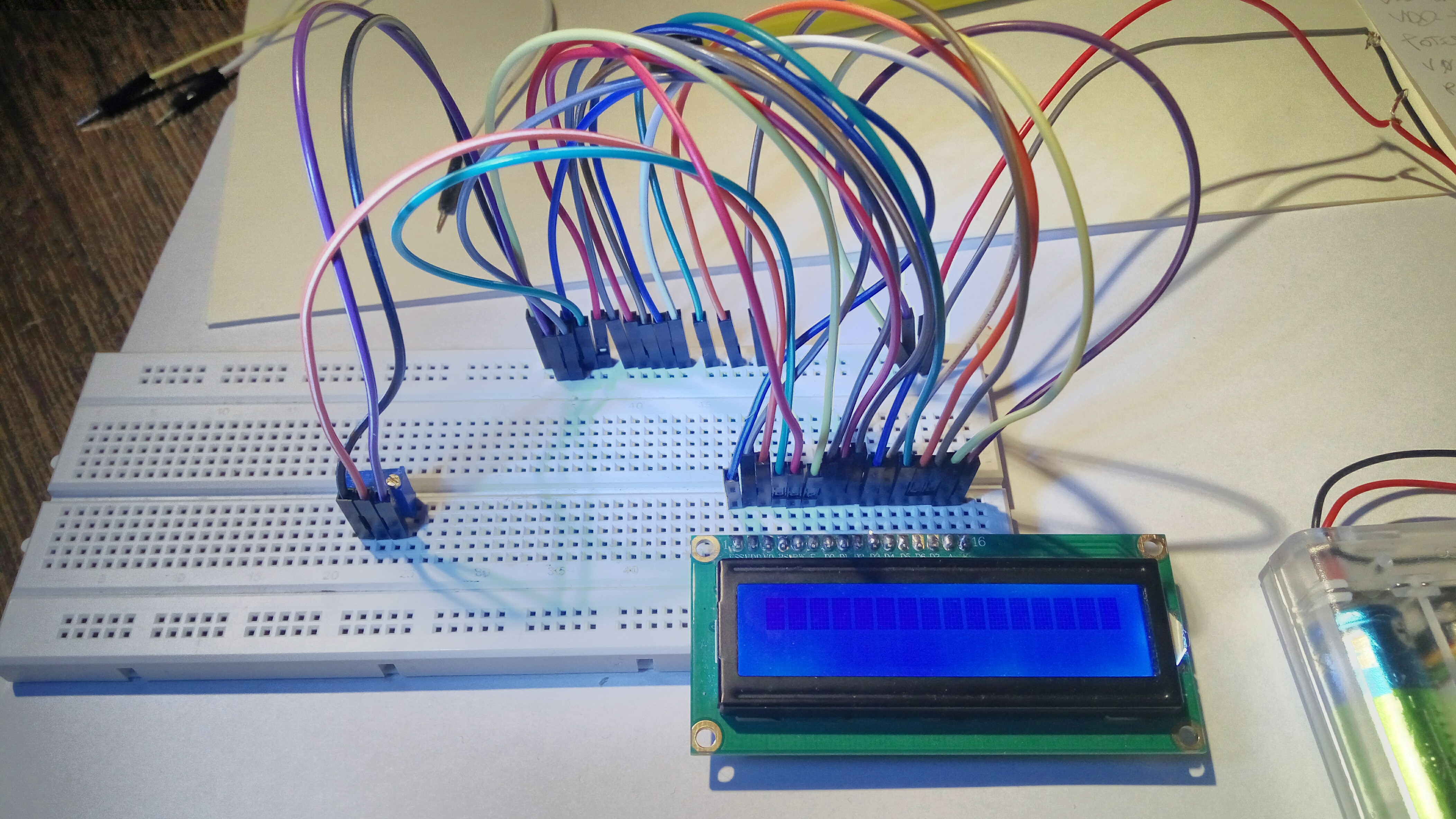
Do opisanych tu zabaw użyłem: wyświetlacz LCD z kontrolerem HD44780, płytkę prototypową, koszyczek na cztery baterie AA, opornik 10 kiloomów, pushbutton, potencjometr montażowy 10 kiloomów, dużo przewodów do łączenia tego wszystkiego.
For this experiment I used: LCD display with HD44780 controller, breadboard, battery holder for four AA batteries, 10 kiloohm resistor, pushbutton, 10 kiloohm trimmer potentiometer, a lot of cables.
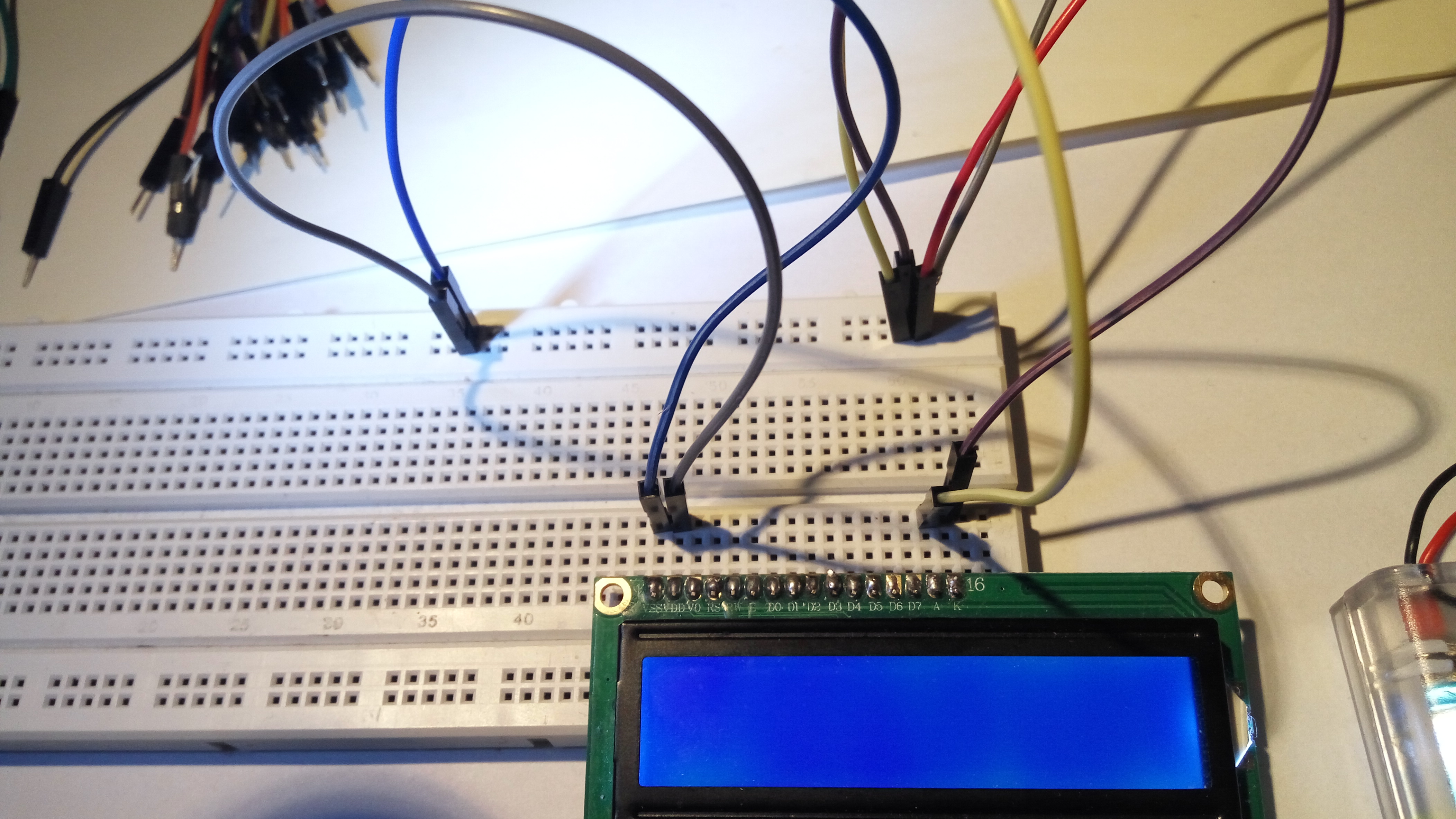
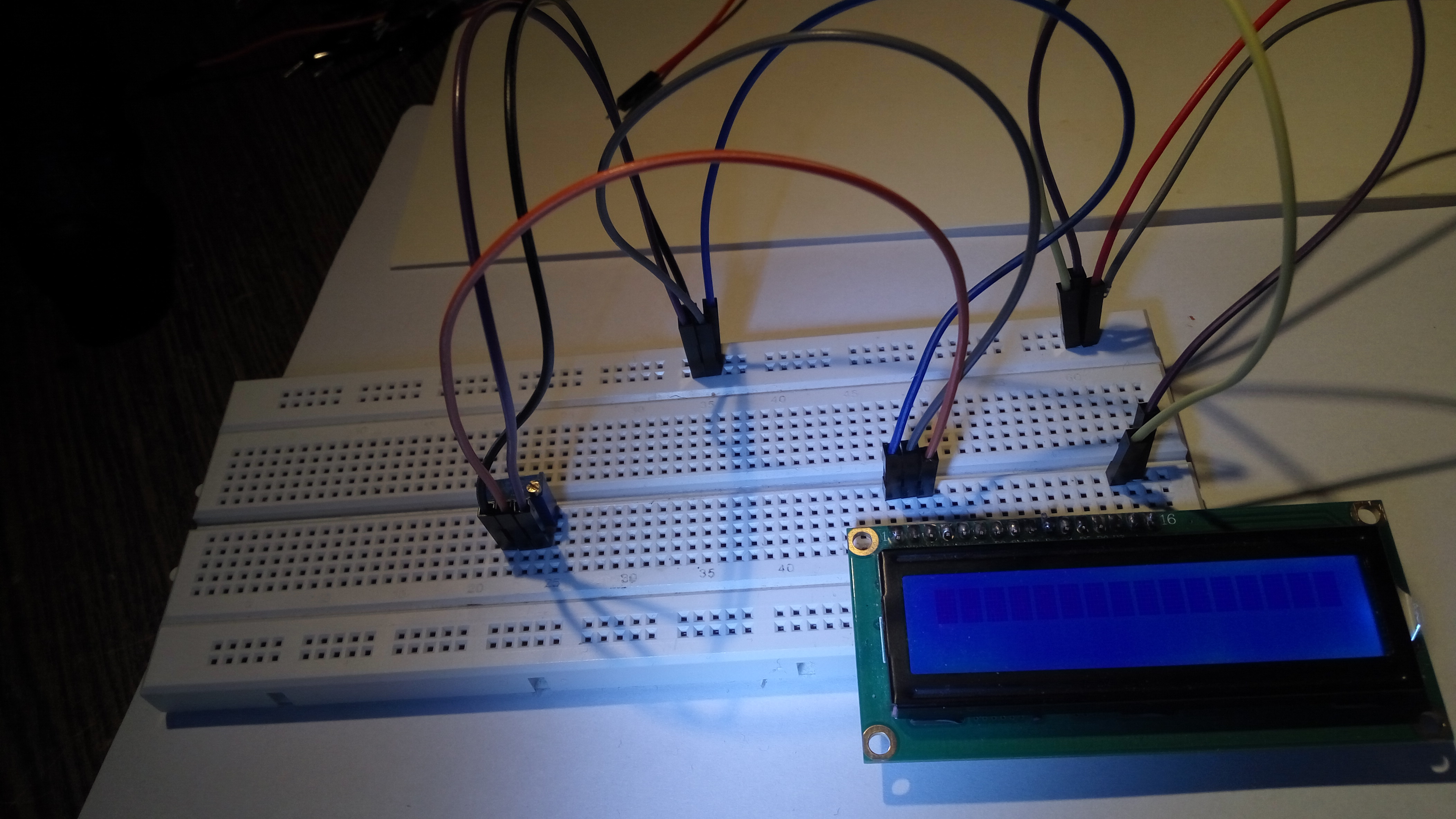
Ten wyświetlacz potrzebuje zasilania od 3,3 V do 5 V. Więc wziąłem cztery akumulatorki AA (każdy ma 1,2 V, więc razem mają 4,8 V, czyli prawie 5 V), włożyłem je do koszyczka i podpiąłem do breadboarda. Wpiąłem w breadboard wyświetlacz. Nóżki wyświetlacza A i K (zasilające podświetlenie wyświetlacza) podpiąłem do masy i +5 V (tych z baterii) - A podpiąłem do plusa, a K do masy. Nie przejmowałem się przy tym tym, że w Internecie radzą, żeby podświetlenie podpinać przez opornik 220 omów - ja podpiąłem bez opornika i też było dobrze. W efekcie podświetlenie wyświetlacza zaczęło świecić.
This display needs power between 3.3 V and 5 V. So I took four AA rechargeable batteries (each has 1.2 V, so they have 4.8 V together - almost 5 V), I put them in the basket and attached them to the breadboard. I connected the display to the breadboard. I connected display pins A and K (supplying display backlight) to ground and +5 V - A to plus and K to ground. I didn't care about Internet advises to connect the backlight through a 220 ohm resistor - I connected it without a resistor and it worked. As a result, the display backlight began to glow.

Teraz podłączyłem zasilanie do elektroniki wyświetlacza. W tym celu nóżkę VSS wyświetlacza podłączyłem do uziemienia, a nóżkę VDD wyświetlacza podłączyłem do +5 V baterii. To na razie nie dało żadnego zauważalnego efektu.
Now I connected power supply to the display: I connected VSS pin of the display to ground and I connected VDD pin of the display to +5 V of battery. It didn't cause any visible effect yet.
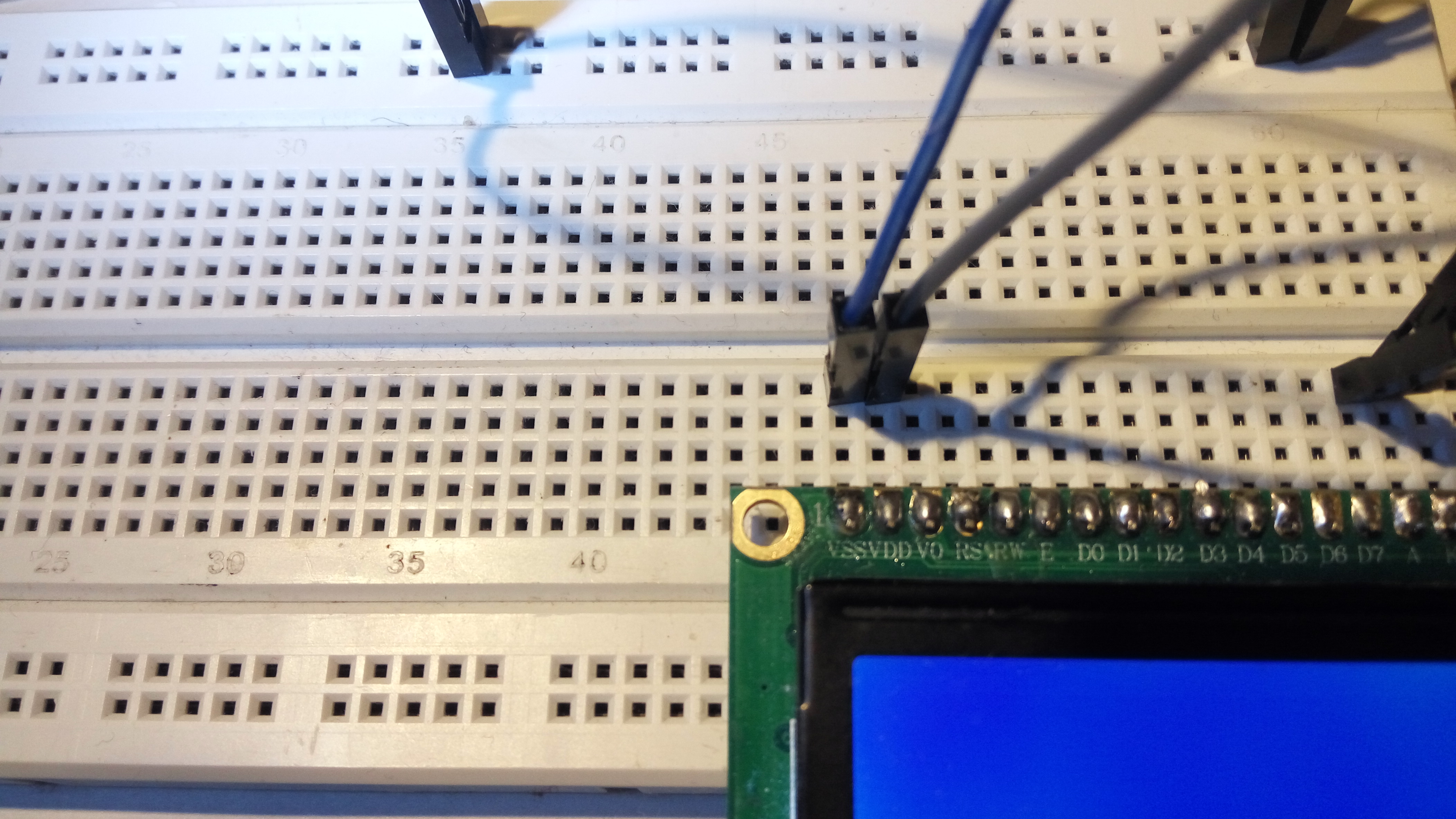
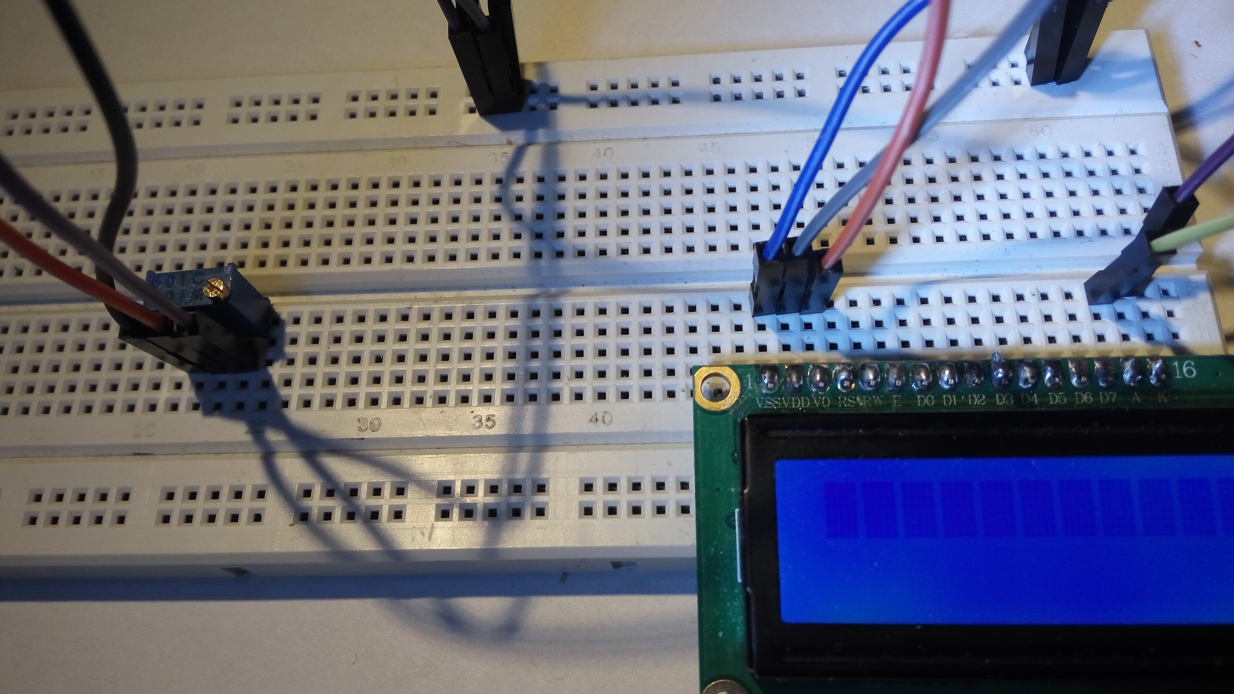
Teraz podłączyłem prąd do kontrastu wyświetlacza, żeby było na nim widać to, co jest wyświetlane. W tym celu trzeba podłączyć nóżkę V0 do +5 V przez potencjometr. Więc wziąłem potencjometr montażowy 10 kiloomów i podłączyłem jego skrajne nóżki do uziemienia i do +5 V (wszystko jedno którą nóżkę do czego).
Now I connected electricity to the display contrast, so we can see what the display displays. In order to do it I have to connect V0 pin of the display through potentiometer. So I took 10 kiloohm trimmer potentiometer and I connected its outer (left and right) pins to ground and +5 V (it doesn't matter which of the two potentiometer pins is connected to what).
A teraz środkową nóżkę potencjometra podłączyłem do nóżki V0 wyświetlacza. Pokręciłem potencjometrem, aż na wyświetlaczu pojawiły się wyraźne czarne kropki.
Then I connected middle pin of the potentiometer to V0 pin of the display. I regulated the potentiometer, so black dots appeared on the display.

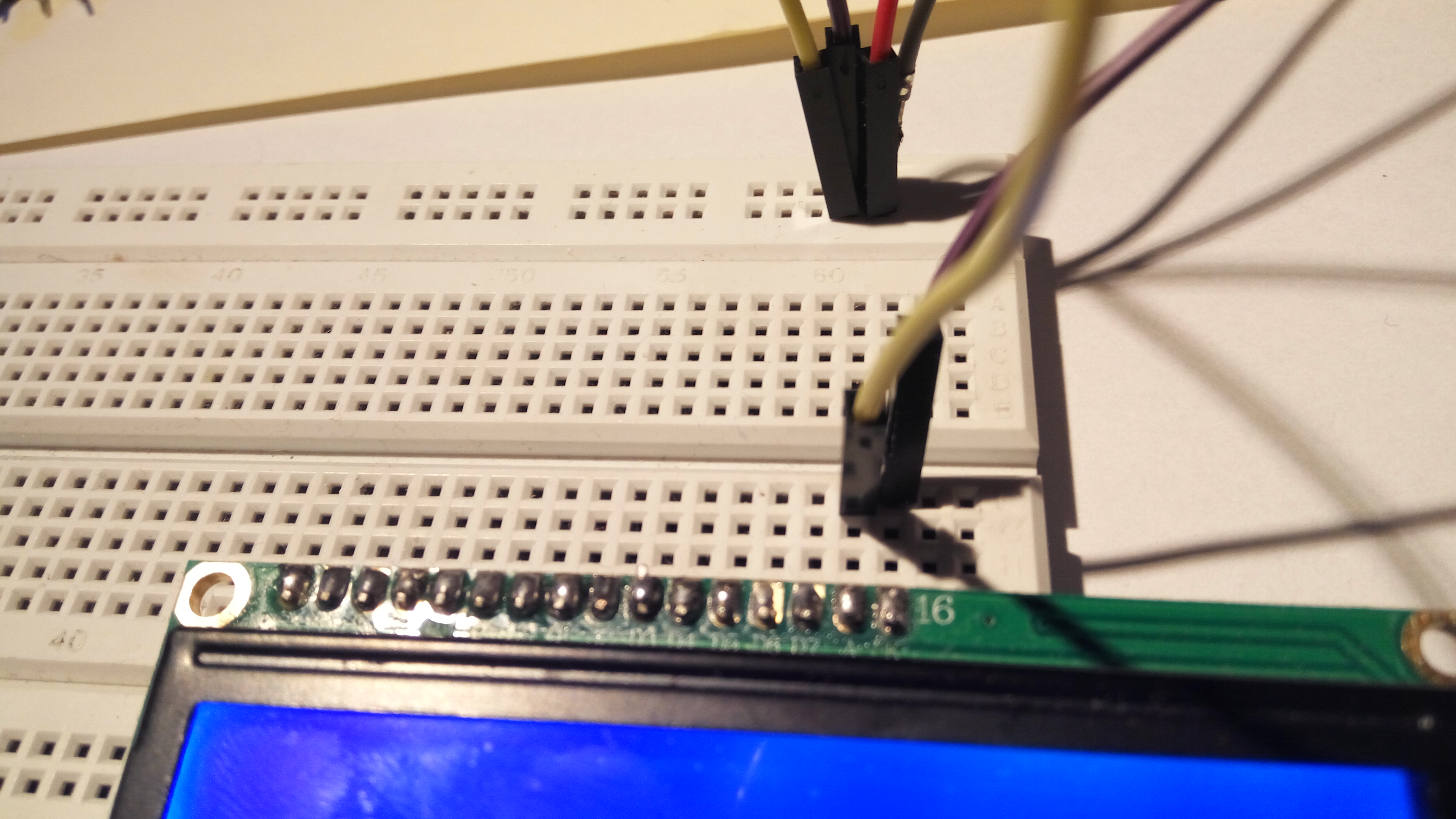
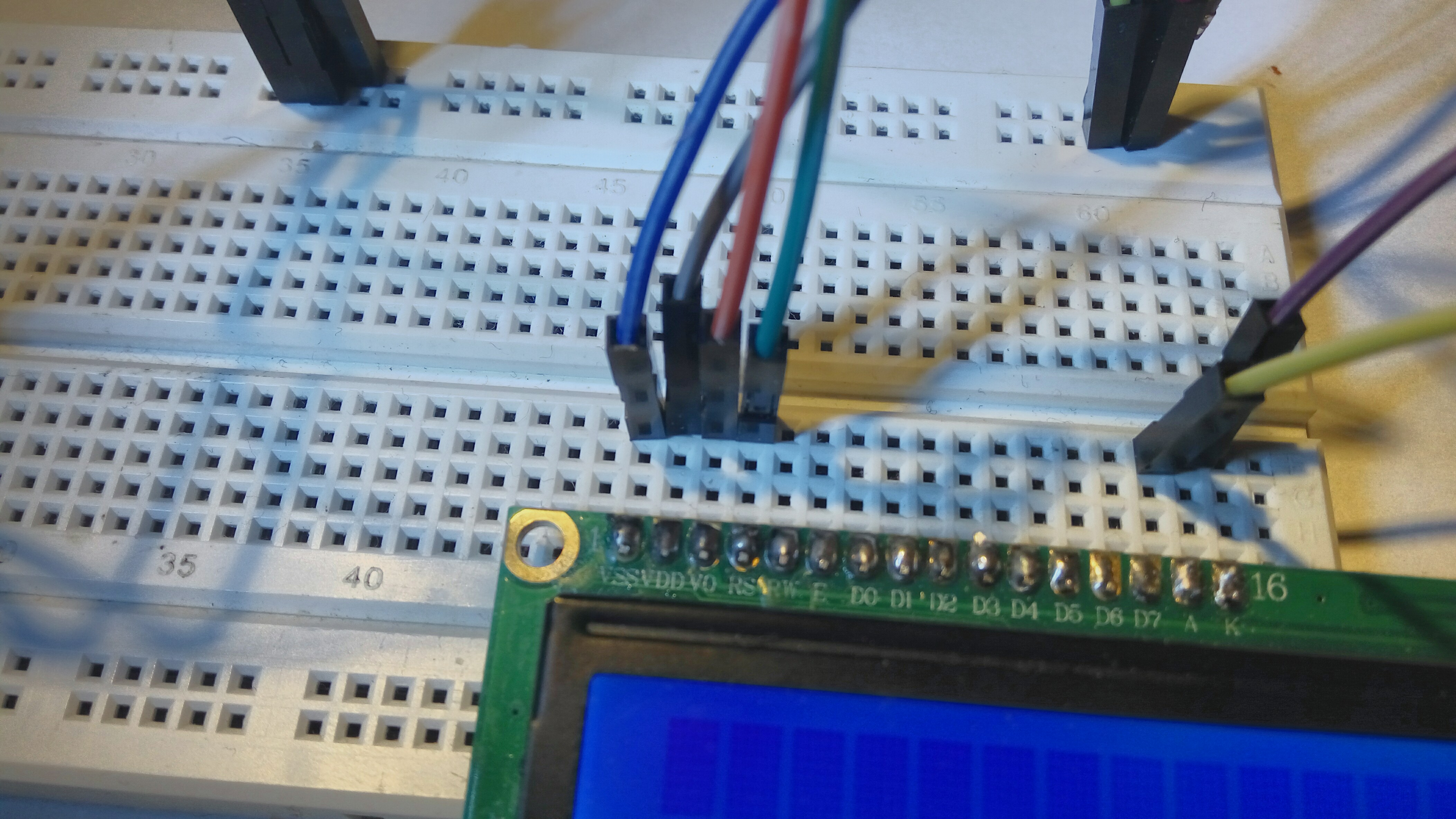
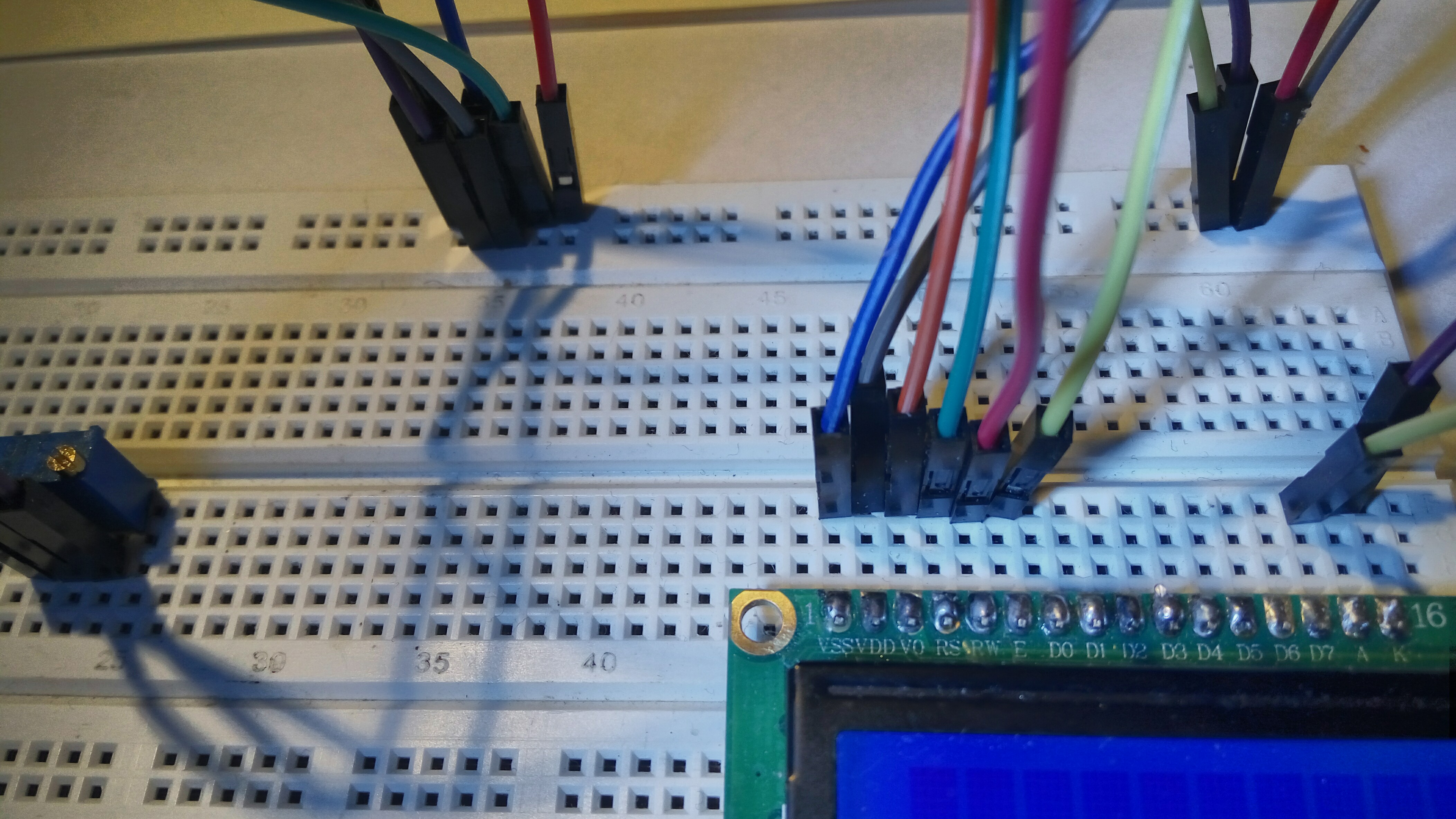
Teraz będę podłączał te nóżki wyświetlacza, które służą do programowania go (czyli do wysyłania poleceń do wbudowanego w wyświetlacz kontrolera HD44780).
Now I will connect these display pins which are used to program the display (that is, to send commands to HD44780 controller embedded in the display).
Najpierw podłączyłem nóżkę RS do masy. To jest nóżka, która służy do powiedzenia wyświetlaczowi, czy to, co będziemy mu wysyłać, to są polecenia (na przykład ustaw kursor tu-a-tu) czy też dane (na przykład litery, które mają być wyświetlone). Na początek podłączyłem tę nóżkę do masy, co oznacza wysyłanie poleceń.
First, I connected the RS pin to ground. This is a pin that is used to tell the display if the signals which we will send it are commands (e.g. set the cursor here) or data (e.g. letters to be displayed). At the beginning I connected this pin to ground, which means sending commands.
Potem podłączyłem nóżkę RW do masy. To jest nóżka, która służy do mówienia wyświetlaczowi, czy chcemy wysyłać do niego sygnały (na przykład żeby wyświetlacz litery na wyświetlaczu), czy też chcemy odbierać od niego sygnały (na przykład żeby odczytywać litery z wyświetlacza). My będziemy tylko wysyłać sygnały, więc dlatego podłączyłem tę nóżkę do zera (masy) i już nie będę tego zmieniał aż do końca eksperymentu.
Then I connected the RW pin to the ground. This is a pin that is used to tell the display whether we want to send signals to it (for example, to display letters on the display) or whether we want to receive signals from it (for example, to read letters from the display). We will only send signals, so that's why I connected this pin to zero (mass) and I will not change it until the end of the experiment.
Potem podłączyłem nóżkę E do masy. Ta nóżka będzie służyła do uruchamiania poleceń - kiedy na tę nóżkę dam na chwilę 1, to w momencie kiedy 1 z powrotem zmieni się w 0, polecenie ustawione na nóżkach D0-D7 (o nich będzie za chwilę) wykona się.
Then I connected pin E to the ground. This pin will be used to run commands - when I put 1 on this pin for a while, then when 1 turns back to 0, the command set on legs D0-D7 (I will talk about them in a moment) will be executed.
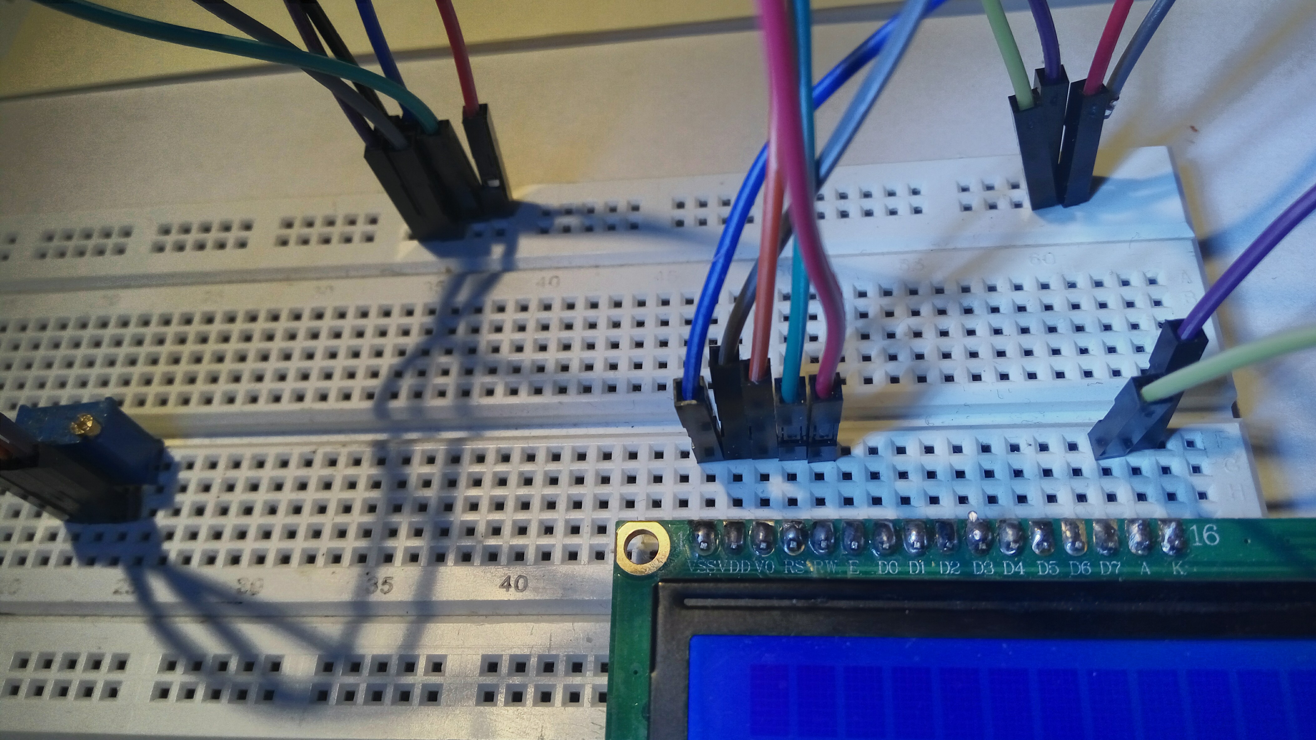
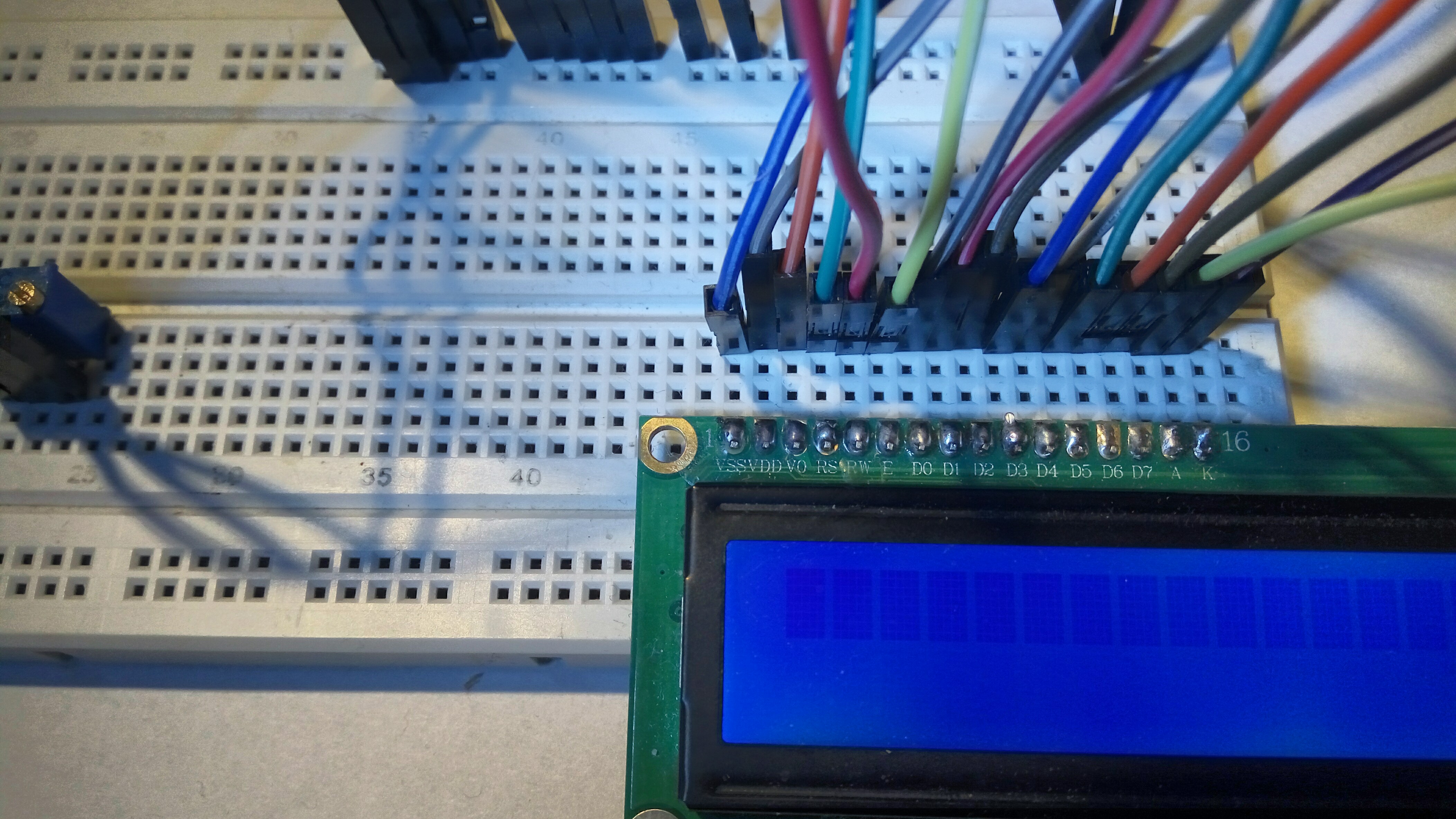
Potem podłączyłem nóżki D0, D1, D2, D3, D4, D5, D6 i D7 do masy (czyli dałem na nie 0). To są te nóżki, na których będę ustawiał jedynkami i zerami, jaki polecenie ma zostać wykonane.
Then I connected the pins D0, D1, D2, D3, D4, D5, D6 and D7 to the ground (i.e. I set them to 0). These are the pins which I will use to set (with ones and zeroes) the command which should be executed.
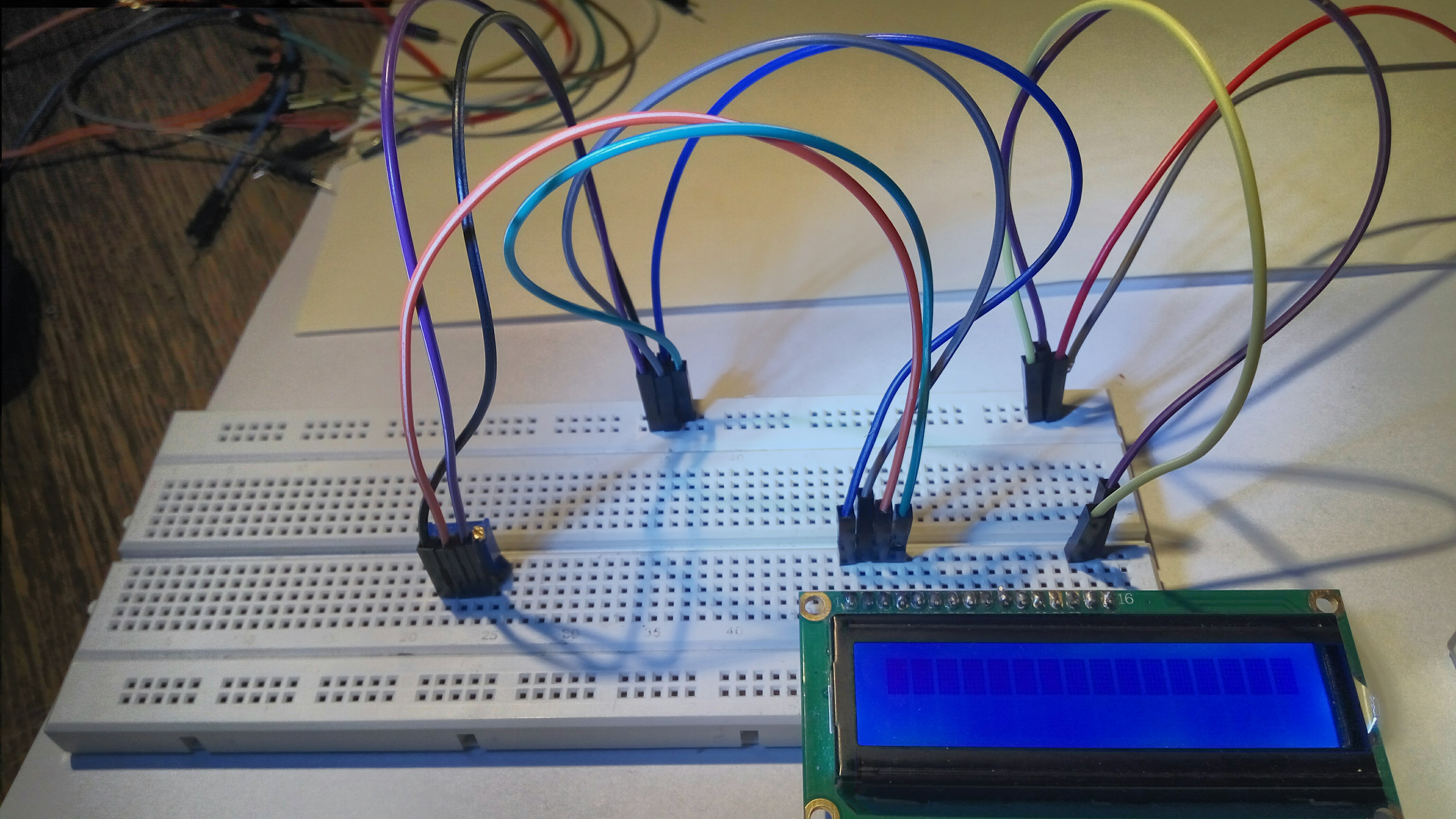
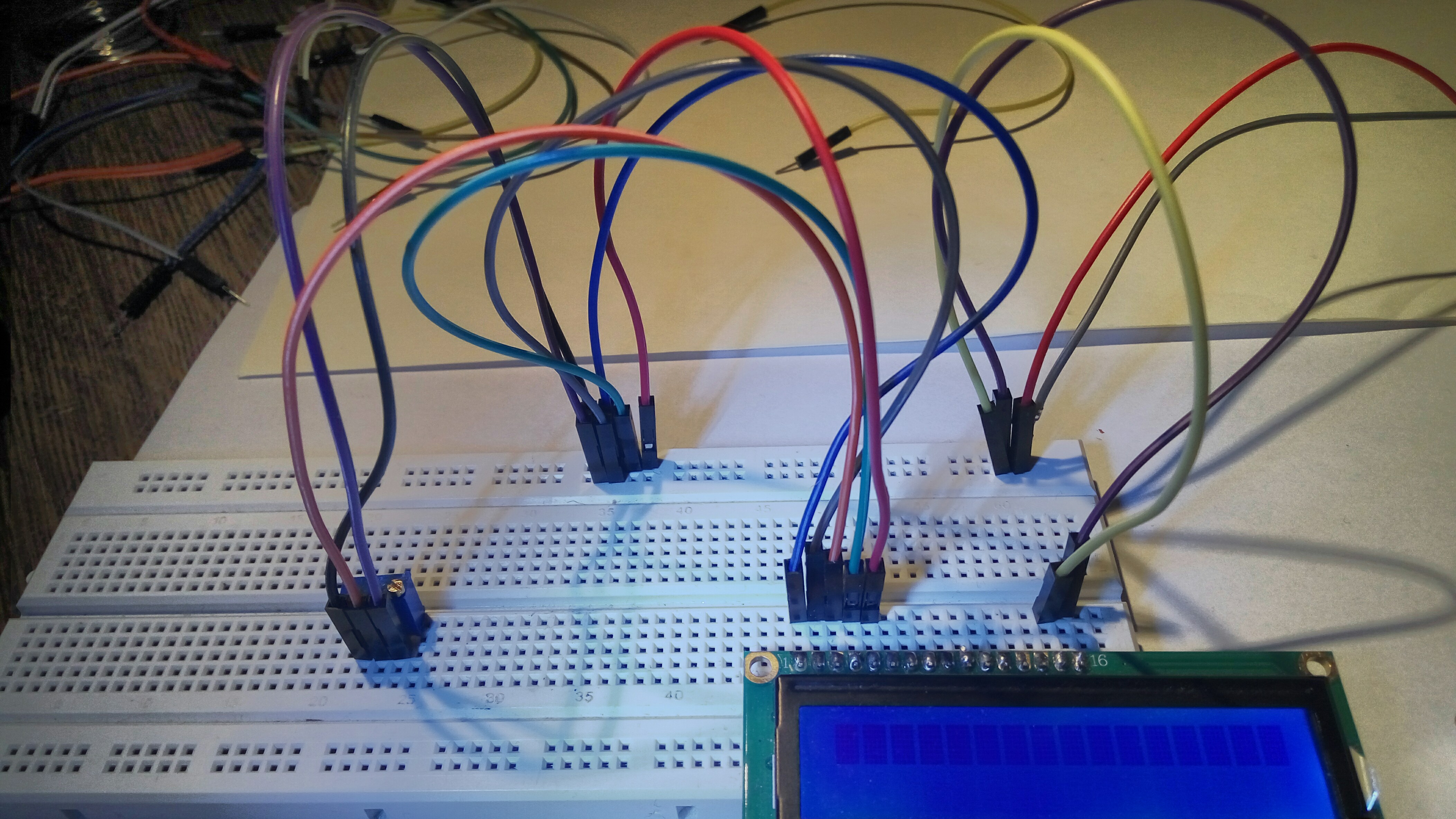
Teraz, kiedy popodłączałem wszystkie potrzebne przewody, mogłem już zacząć wydawać polecenia.
Now that I connected all the necessary cables, I could start sending commands.
Potem przyszła pora, żeby zacząć wysyłać polecenia do wyświetlacza. Najpierw poczytałem sobie na https://mil.ufl.edu/3744/docs/lcdmanual/commands.html jakie są polecenia, potem pobawiłem się symulatorem HD44780 żeby zrozumieć jak działają te polecenia, a potem zacząłem wysyłać polecenia przez przełączanie przewodów.
Then came the time to start sending commands to the display. First, I read on https://mil.ufl.edu/3744/docs/lcdmanual/commands.html what are the commands, then I played with HD44780 simulator to understand how the commands work, and then I started sending commands by reconnecting cables.
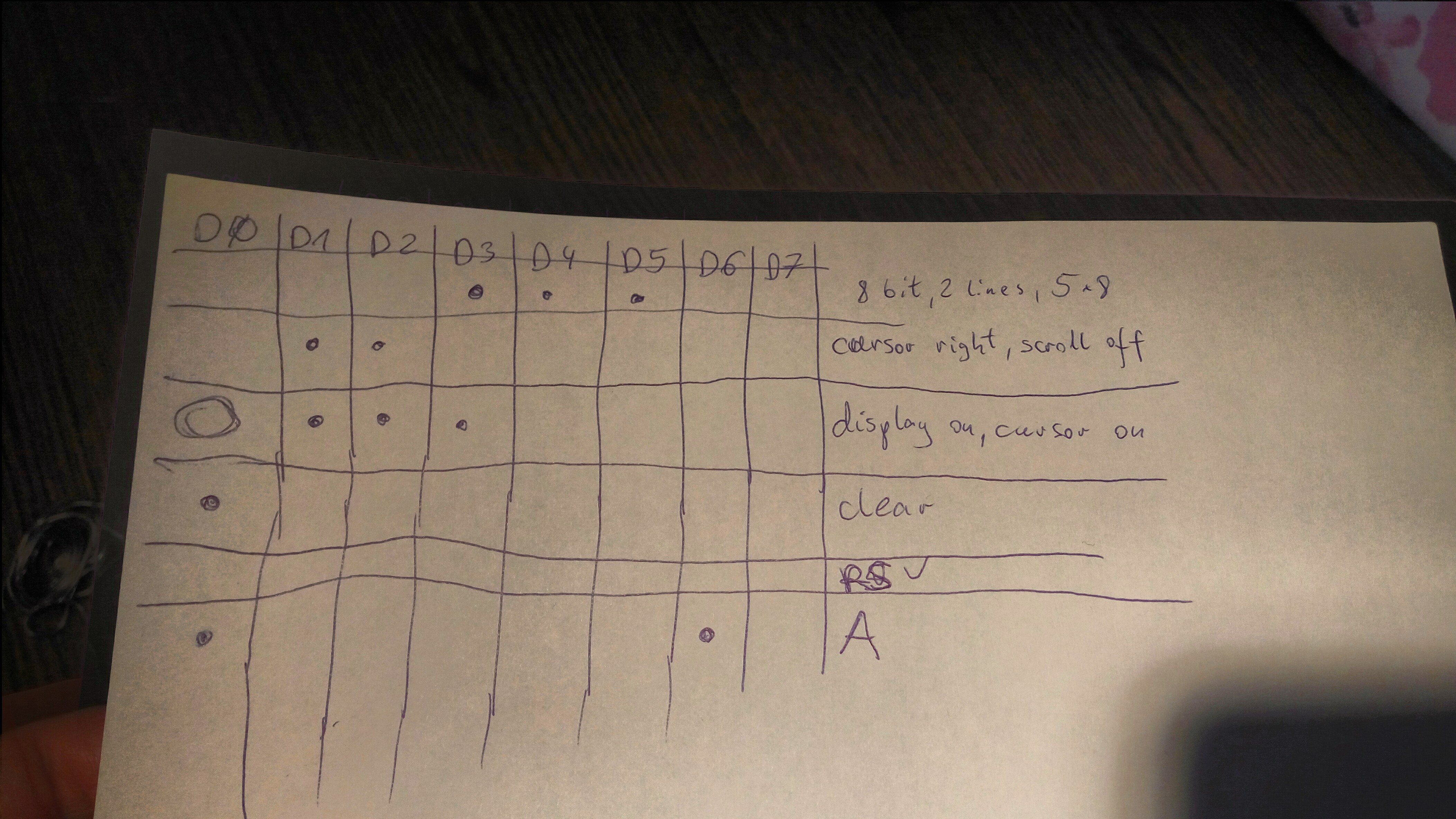
Najpierw musiałem ustawić wyświetlacz w odpowiedni tryb. Ustawiłem na nóżkach D0-D7 polecenie 00011100 - czyli polecenie tryb ośmiobitowy, dwulinijkowy, 5x7. To jest polecenie, które ustawia wyświetlacz w tryb dwulinijkowy (to znaczy, że wyświetlacz będzie wyświetlał dwie linijki tekstu), wielkość znaków ustawia na 5x7 (to znaczy, że każdy znak ma mieć 5x7 pikseli) a tryb wysyłania poleceń ustawia na tryb ośmiobitowy (to znaczy, że każde polecenie będzie wysyłane jako osiem bitów ustawionych na nóżkach D0-D7). To polecenie ustawiłem tak, że poszczególne nóżki ustawiłem tak, jak każą odpowiednie bity, a więc D0 podłączyłem do masy, D1 podłączyłem do masy, D2 podłączyłem do masy, D3 podłączyłem do plusa, D4 podłączyłem do plusa, D5 podłączyłem do plusa, D6 podłączyłem do masy, D7 podłączyłem do masy.
First, I had to set the display to the correct mode. On D0-D7 pins I set the 00011100 command - i.e. the eight-bit, two-line, 5x7 command. This is the command that sets the display to two-line mode (that is, the display will display two lines of text), the glyph size is set to 5x7 (that is, each glyph is to be 5x7 pixels) and the command sending mode is set to eight-bit mode (this means that each command will be sent as eight bits set on pins D0-D7). I set this command in such a way that I set the pins according to the bits, so D0 is connected to ground, D1 is connected to the ground, D2 is connected to the ground, D3 is connected to plus, D4 is connected to plus, D5 is connected to plus, D6 is connected to the ground, D7 is connected to the ground.
Wtedy uruchomiłem to polecenie: w tym celu nóżkę E podłączyłem na chwilę do plusa, a potem z powrotem podłączyłem do masy. Bo HD44780 działa tak, że jak dostanie napięcie na nóżkę E, to odczytuje polecenie z nóżek D0-D7 i je wykonuje.
Then I executed the command: for this purpose I connected the E pin to the plus, and then connected it again to the ground. This is how HD44780 works - when it gets voltage on the E foot, it reads the command from the D0-D7 feet and executes it.

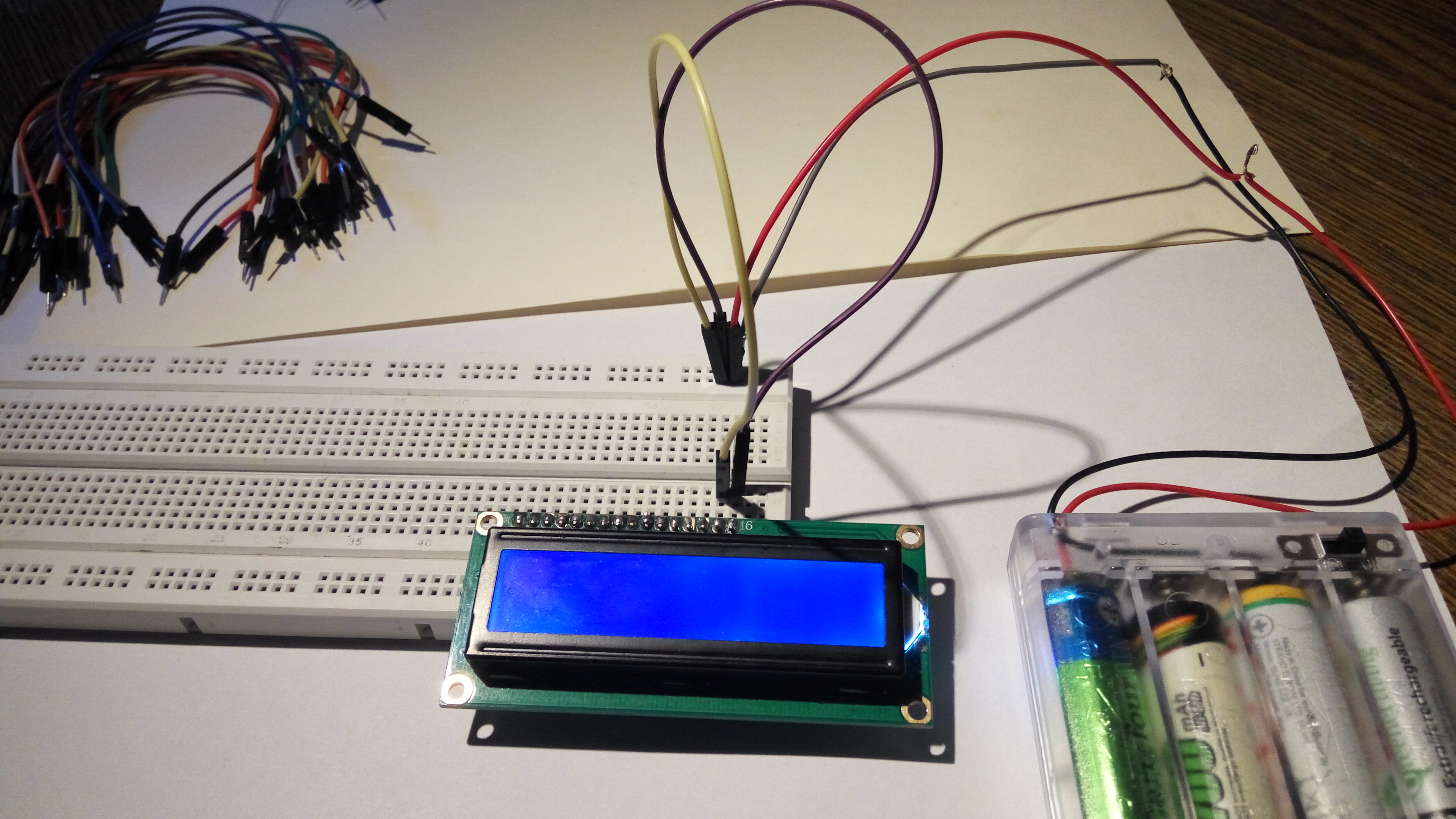
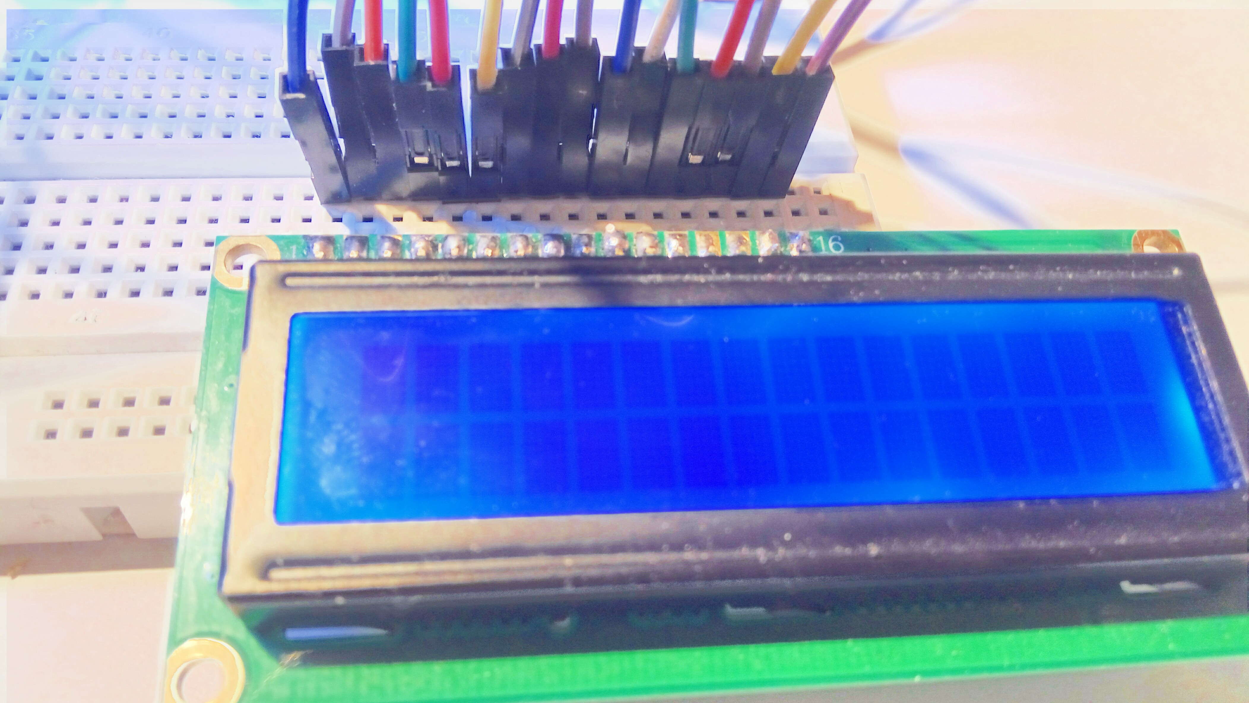
To był ważny moment: bo już od dłuższego czasu podłączałem różne przewody, ale nie miałem jak się przekonać, że to, co robię, robię dobrze, bo to, co robiłem, nie dawało żadnego widocznego efektu. Na szczęście teraz wykonanie polecenia 00011100 dało widoczny efekt: na wyświetlaczu, na którym dotąd była widoczna jedna linijka ciemnych komórek służących do wyświetlania znakow, teraz pojawiły się dwie takie linijki.
It was an important moment: until this moment I had been connecting pins and cablescables for a long time, but I couldn't know if I was doing it right, because what I was doing had no visible effect. Fortunately, now the execution of the 00011100 command has had a visible effect: on the display, which until now displayed one line of dark cells used to display characters, now two such lines have appeared.
Potem wykonałem jeszcze dwa polecenia. Najpierw wykonałem polecenie 01100000 (czyli: D0=0, D1=1, D2=1, D3=0, D4=0, D5=0, D6=0, D7=0) - to jest polecenie: "cursor right, scroll off", ono powoduje, że w trakcie wyświetlania napisów kursor przesuwa się w prawo, a ekran nie skroluje. A potem wykonałem polecenie 11110000 (czyli: D0=1, D1=1, D2=1, D3=1, D4=0, D5=0, D6=0, D7=0) - to jest polecenie: "display on, cursor on, blink on", ono powoduje, że wyświetlanie napisów jest włączone, kursor jest widoczny i migający.
Then I executed two more instructions. First, I executed the 01100000 command (i.e.: D0=0, D1=1, D2=1, D3=0, D4=0, D5=0, D6=0, D7=0) - this is the command: "cursor right, scroll off", it causes the cursor to move right when a text is displayed, and the screen will not scroll. And then I executed the command 11110000 (i.e.: D0=1, D1=1, D2=1, D3=1, D4=0, D5=0, D6=0, D7=0) - this is the command: "display on, cursor on, blink on", it causes the display to be turned on, the cursor to be visible and flashing.
Po wykonaniu tego polecenia kursor na wyświetlaczu zaczął migać.
After executing this command, the cursor on the display began to flash.

Potem wydałem polecenie 10000000 (czyli: D0=0, D1=1, D2=1, D3=0, D4=0, D5=0, D6=0, D7=0) - to jest polecenie "clear", ono czyści wszystko co jest wyświetlone na wyświetlaczu i umieszcza kursor na początku wyświetlacza. To polecenie nie daje żadnego zauważalnego efektu.
Then I gave the command 10000000 (i.e.: D0=0, D1=1, D2=1, D3=0, D4=0, D5=0, D6=0, D7=0) - this is the "clear" command, it cleans everything which is shown on the display and places the cursor at the beginning of the display. This command has no visible effect.
Potem przełączyłem pin RS z masy (czyli trybu wysyłania poleceń) do plusa (czyli w tryb wysyłania napisów do wyświetlenia).
Then I switched the RS pin from ground (i.e. from command sending mode) to plus (i.e. into the mode in which we will send the text to be displayed).
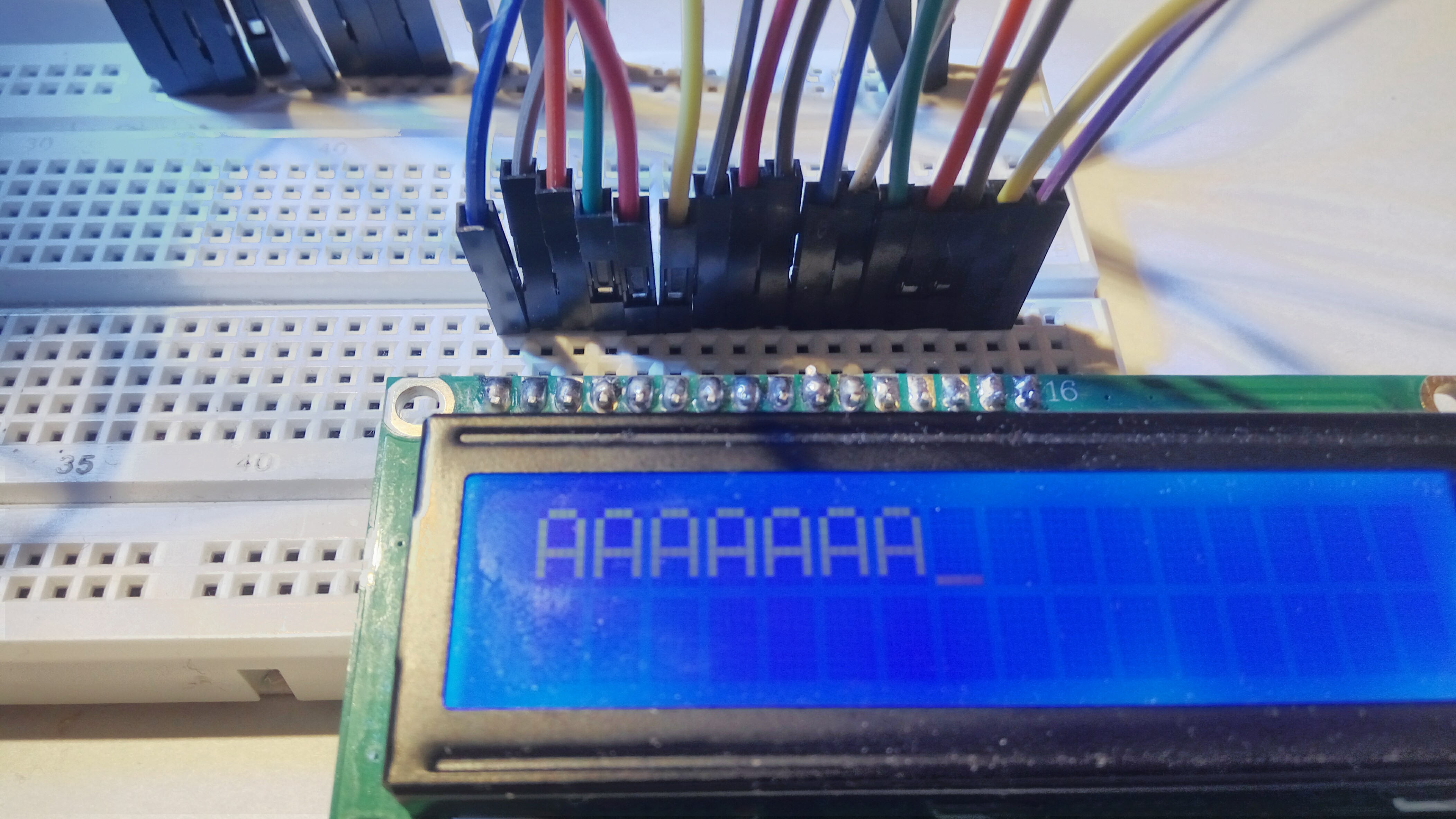
Wtedy wysłałem do wyświetlenia literę A. W tym celu ustawiłem piny D0-D7 na 10000010 (czyli: D0=1, D1=0, D2=0, D3=0, D4=0, D5=0, D6=1, D7=0) i zatwierdziłem to na chwilę podłączając pin E do plusa (a potem z powrotem przełączając go na masę).
Then I sent the letter A. To do this, I set pins D0-D7 to 10000010 (i.e.: D0=1, D1=0, D2=0, D3=0, D4=0, D5=0, D6=1, D7=0) and confirmed it for a moment by connecting the E pin to the plus (and then switching it back to ground).
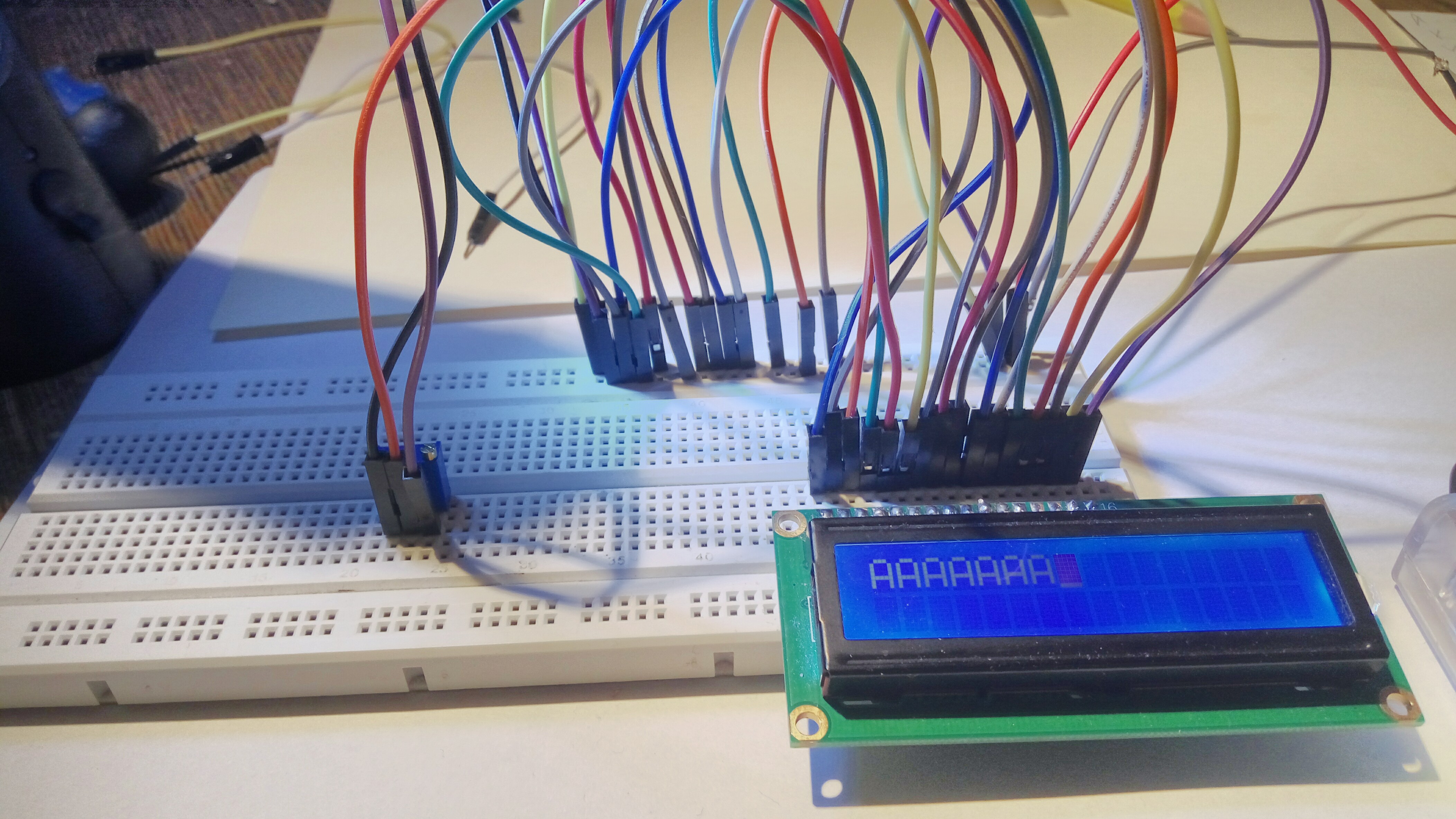
I jak tylko puściłem sygnał na nóżkę E, na wyświetlaczu wyświetliło się kilka liter A. Teoretycznie powinna pojawić się tylko jedna litera A. Myślę, że pojawiło się ich kilka dlatego, że wtykając przewód w breadboarda trudno jest puścić tylko jedną jedynkę: w momencie wtykania przewód przez chwilę nie kontaktuje, więc zamiast jednej jedynki idzie seria jedynek przerywana zerami, i każda taka jedynka wyświetla jedno A.
And as soon as I released the signal on the pin E, a few letters A appeared on the display. Theoretically, only one letter A should appear. I think that there were several of them because it is difficult to send just one 1 by sticking the wire in the breadboard: the wire does not contact for a moment, so instead of one 1 I send a series of 1s seperated by 0s, and each such 1 displays one A.
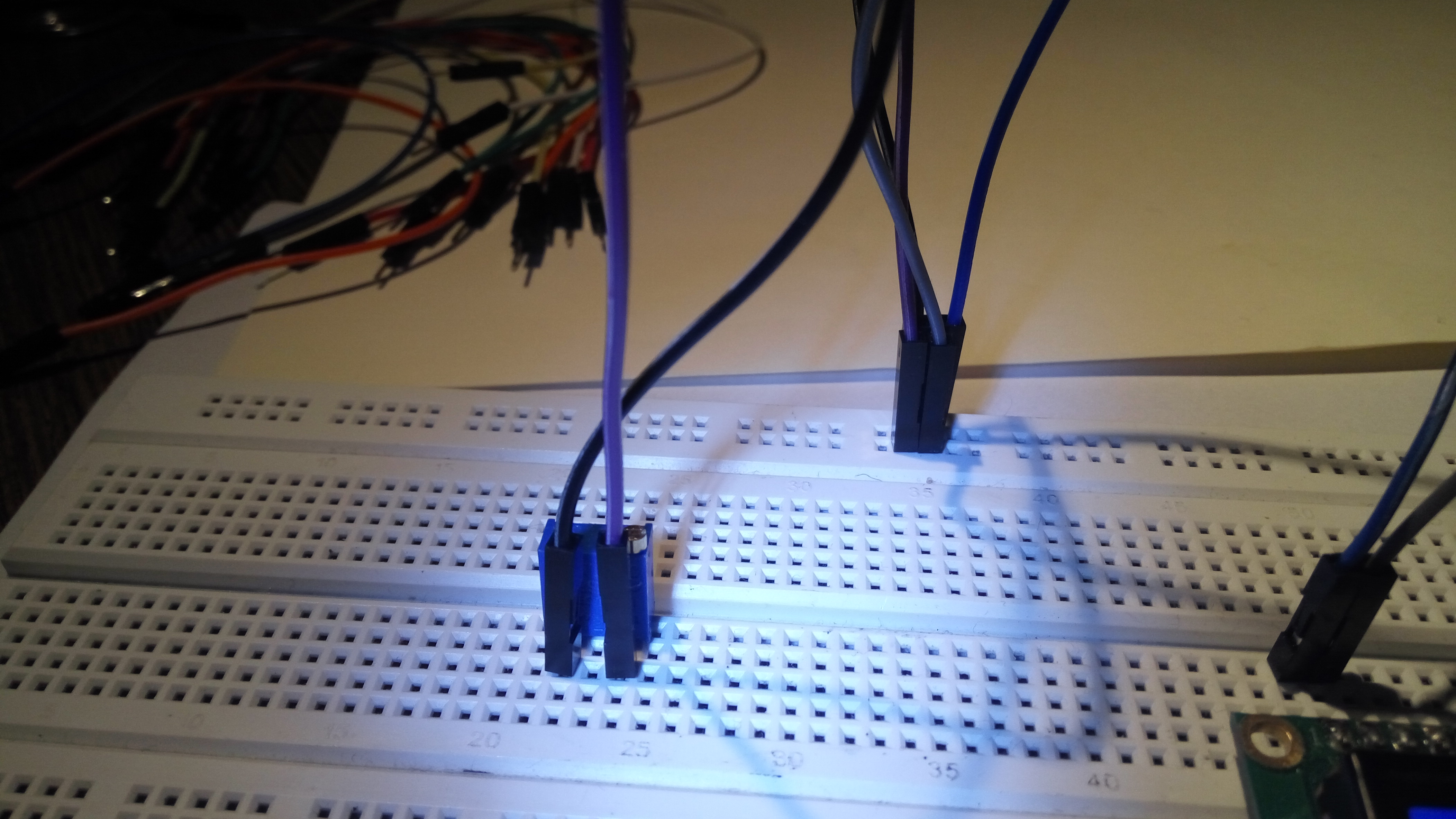
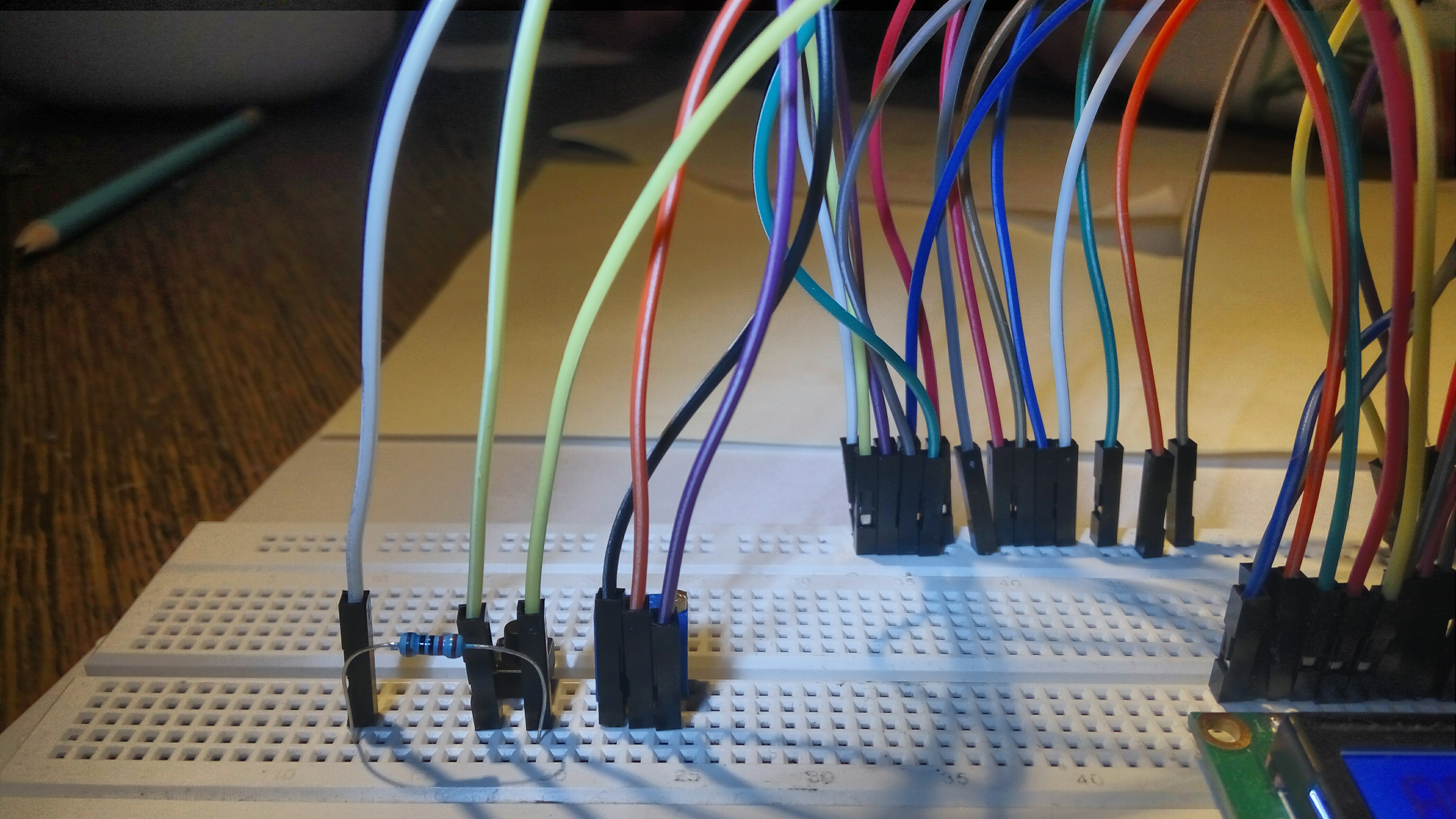
A potem przerobiłem trochę mój układ tak, żeby móc wysyłać pojedyńcze jedynki. W tym celu nóżkę E podłączyłem do plusa przez pushbutton...
And then I converted my layout a little so that I could send single ones. To this end, I connected the E pin to +5V through a pushbutton...

... i jeszcze podłaczyłem nóżkę E przez jakiś opornik pulldown do masy.
... and I connected the E pin via a pulldown resistor to the ground.
Po czym wysyłałem kolejne polecenia, napisy do wyświetlenia itp. Koniec.
After which I sent further commands, text to display, etc. The end.